The Room Around the Equipment: A Refurbishment Checklist for UK Water Treatment Access
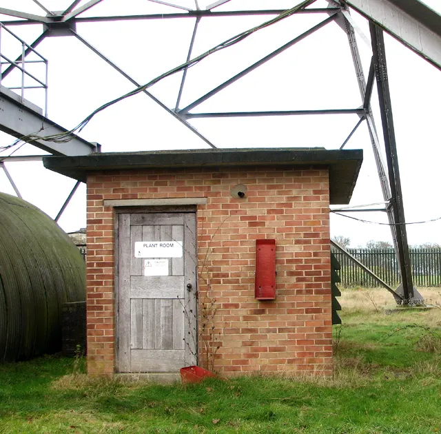
Photo: Evelyn Simak , CC BY-SA 2.0, via Wikimedia Commons
Refurbishment projects in UK plant rooms tend to follow a familiar sequence. Heating, ventilation, electrical and major water services are fixed first; water treatment is then asked to fit around them. Filtration housings, dosing equipment, sample points and drains arrive at the coordination stage as a series of small requirements, by which time the useful space has already been allocated. The result is not usually a dramatic failure. It is a slow accumulation of awkward access, improvised containment and maintenance routines that depend on isolation valves being reached over pipework.
A better approach is to treat water treatment as a spatial system with its own clearances, routes and service needs. The aim is not to give treatment plant more room than it needs, but to ensure the room it needs is identified before the layout is frozen.
The treatment envelope
Design reviewers can think of this as a treatment envelope: the footprint of the equipment plus the working space around it, the route by which chemicals and replacement parts reach it, the containment that catches spills, and the access needed for isolation and sampling. The envelope is not a single drawing layer. It is a set of questions that should be asked at concept design and answered again at spatial coordination.
Filter-change clearance and the working aisle
Filters are a useful test case. A cartridge or bag filter housing may occupy less than a square metre, but changing it requires upstream and downstream isolation, a drain connection, space to remove the housing or bowl, a tray or floor drain for residual water, and enough height to lift the element without striking services. Housings mounted high on a wall may look tidy on a drawing; in operation they require steps, a platform or a contractor with a ladder. In a refurbishment, moving a filter bank after pipework has been installed is rarely a simple task.
The same logic applies to strainers, softener vessels and UV reactors. Each item needs a working aisle, not merely a footprint. A useful check is to mark on the drawing where the maintenance technician will stand, where the removed component will be placed and where the displaced water will go.
Sample points within safe reach
Sample points should be reachable from standing height, with a drip tray and a drain nearby, and located on the correct side of the treatment step. A sample tap that requires a ladder is not a practical compliance tool; a tap that discharges across a walkway is a slip risk. The point should be labelled with its system and purpose, and the route from the tap to the sample bottle should be short enough that the person taking the sample can manage the bottle, the lid and the log sheet without improvising. Where chlorine residual, pH or temperature are measured on site, a small shelf or bench helps.
Chemical delivery, decanting and spill containment
Chemical delivery routes are often overlooked because they cross departmental boundaries. A 25-litre container is manageable; a 200-litre drum is not. The route from the delivery vehicle to the dosing tank needs to be measured, not assumed: door widths, thresholds, ramps, lifts and turning circles all matter. Secondary containment should be sized for the largest container and arranged so that a spill does not reach a drain, a walkway or electrical equipment. Decanting points need ventilation, eye wash and a clear separation from potable water services. Guidance on backflow and fluid category separation should be checked against the Water Supply (Water Fittings) Regulations 1999 and WRAS guidance. If the delivery route passes through a reception area or a kitchen corridor, the design has already failed the practical test.
Isolation access and the shutdown map
Isolation access is the difference between a planned maintenance task and an unplanned shutdown. Valves should be reachable, labelled and, where appropriate, lockable. Strainers need space for basket removal. Softener brine tanks need room for salt delivery and for the lid to be lifted. UV reactors need clearance for lamp and sleeve replacement, plus the electrical isolation that goes with it. A simple rule is to ask the person who will do the task to stand in the space on the drawing, with the tools and parts they will carry. If the drawing has no space for that person, the layout is not complete.
A shutdown map should be part of the handover pack. It should show which valves isolate the filter bank, the dosing line, the softener and the sample points, and it should match the labels in the room. Under the HSE's L8 Approved Code of Practice, the control scheme depends on being able to operate the system as designed; access to isolation is part of that practical capability.
Drains, power and the unglamorous services
Drains, power and data are the services that make treatment work. A floor drain near the filter bank and sample point is more useful than a distant gully. A power socket for a dosing pump should not be located directly beneath a potential leak. Controls and telemetry need a clean signal path and a labelled panel. Lighting should be sufficient to read gauges and labels; ventilation should remove chemical vapours from the dosing area. None of these items is expensive at design stage. All of them become awkward once the ceiling grid is closed.
Reviewing the refit at the right gate
The practical solution is to introduce a water treatment design review at three points: concept, spatial coordination and pre-completion. At concept, the reviewer confirms the treatment duties and the equipment list. At spatial coordination, the reviewer checks the treatment envelope against the room layout and the maintenance routes. At pre-completion, the reviewer confirms that sample points, isolation valves and drains are accessible and recorded. The review should be attended by the mechanical and electrical designer, the water treatment specialist and a representative of the facilities team who will inherit the room. A signed checklist is more useful than a general assurance that access has been considered.
Conclusion
Water treatment is not an afterthought that can be threaded through a finished plant room. It is a set of equipment and activities that occupy space, require services and need to be maintained safely. In UK refurbishments, the cheapest place to solve a clearance problem is on the drawing. The most expensive place is after the pipework has been insulated, the ceiling has gone in and the first filter needs changing.